
Microfarad Symbol: µF Meaning & How to Read It
The microfarad symbol, µF, is commonly seen on capacitors, circuit diagrams, electronic components, repair manuals, and electrical specifications. It represents a unit of capacitance called the microfarad, which is one millionth of a farad. Capacitors use this unit because a full farad is often much larger than the capacitance values needed in everyday electronic circuits. When you see a marking such as 10 µF, 100 µF, or 470 µF, it tells you the capacitance value of the component. Understanding the symbol makes it easier to identify replacement parts and interpret circuit information. It is especially useful when working with power supplies, audio equipment, appliances, and hobby electronics.
The microfarad is part of the International System of Units because the farad is the standard SI unit of capacitance. The Greek letter µ, pronounced “micro,” means one millionth, while the letter F stands for farad. Together, µF means microfarad. One microfarad equals 0.000001 farad, or 10⁻⁶ farad. Because capacitor values can vary enormously, engineers also use nanofarads and picofarads for smaller capacitance values. Understanding the relationship between these units helps when reading labels and converting capacitor ratings. It also reduces confusion when different manufacturers express equivalent values in different forms.
Capacitors are electrical components that store energy in an electric field and release it when circuit conditions change. Their capacitance indicates how much electric charge they can store for a given voltage. A larger capacitance value generally means the capacitor can store more charge under the same voltage conditions. This is why microfarad ratings matter in practical circuits. A 1000 µF capacitor behaves very differently from a 1 µF capacitor even if both have the same voltage rating. Selecting the wrong capacitance can cause a circuit to operate incorrectly, so reading µF accurately is an important basic electronics skill.
The µF symbol can sometimes appear differently depending on the device, keyboard, software, or manufacturer. Some labels use “uF” instead of “µF” because the Greek micro symbol is not always easy to type or display. In practical electronics, 10 uF and 10 µF usually mean the same capacitance value. Older components may also use markings that require conversion between microfarads, nanofarads, and picofarads. These variations can make capacitor identification confusing for beginners. Once the common unit relationships are understood, however, most capacitor markings become much easier to interpret accurately.
Learning how to read a microfarad symbol is useful for students, technicians, electricians, electronics enthusiasts, and anyone replacing capacitors in equipment. It helps with understanding circuit diagrams, comparing component specifications, identifying damaged parts, and selecting suitable replacements. Capacitance is only one specification, so voltage rating, tolerance, temperature rating, polarity, and capacitor type must also be considered. Still, the µF value is usually one of the most visible and important markings on a capacitor. The following sections explain what µF means, how microfarads relate to farads, how to read capacitor labels, and how to avoid common mistakes.
What Does the Microfarad Symbol µF Mean?
The µF symbol means microfarad, a unit used to measure electrical capacitance. The symbol is made from the Greek letter µ, which represents the prefix micro, followed by F for farad. In scientific notation, micro means 10⁻⁶, so one microfarad is one millionth of a farad. This unit is practical because many common capacitors have values much smaller than one farad. Instead of writing 0.00001 F, for example, engineers can write 10 µF. The shorter notation is easier to read, compare, print, and place on small electronic components.
Capacitance describes a capacitor’s ability to store electric charge in response to an applied voltage. The standard relationship is based on the amount of charge stored per unit of voltage. A capacitor with greater capacitance can generally store more charge at the same voltage than one with lower capacitance. Microfarad values therefore provide important information about how a capacitor will behave in a circuit. A large electrolytic capacitor might be rated at hundreds or thousands of microfarads. A small timing or filtering capacitor may instead use only a few microfarads or fractions of a microfarad.
The farad itself is a relatively large unit for many traditional electronic applications. This is why smaller units such as microfarads, nanofarads, and picofarads are so common. One microfarad equals 1000 nanofarads, while one nanofarad equals 1000 picofarads. This means 1 µF is equal to 1000 nF and 1,000,000 pF. Recognizing these relationships is useful because circuit diagrams and component labels may use different units for the same value. For example, 0.1 µF can also be written as 100 nF. Both expressions describe the same capacitance.
The capital F in µF is important because it represents the farad, which is named after scientist Michael Faraday. Unit symbols based on people’s names are typically capitalized, even though the written unit name itself is usually lowercase. The micro prefix remains represented by the lowercase Greek µ. Writing “uf” or “UF” may be understandable in informal settings, but µF is the standard technical form. In digital environments where the micro symbol is difficult to enter, “uF” is widely used as a practical substitute. Understanding these variants helps prevent unnecessary confusion when reading online parts listings or technical documents.
The easiest way to remember the symbol is to separate its two parts. The µ tells you the scale, and the F tells you the quantity being measured. Micro means one millionth, while farad is the unit of capacitance. Therefore, 25 µF means twenty-five microfarads, or twenty-five millionths of a farad. Once this interpretation becomes familiar, capacitor labels become much easier to understand. The same prefix system appears in many other measurements, so learning µ also helps with units such as microamps, micrometers, and microvolts.
What Is a Microfarad?
A microfarad is a small unit of capacitance equal to one millionth of a farad. In decimal form, 1 µF equals 0.000001 F. In scientific notation, it can be written as 1 × 10⁻⁶ F. This unit is widely used because many capacitors in everyday electronic equipment fall within the microfarad range. Power supply capacitors, audio coupling capacitors, motor capacitors, and filtering components commonly use values measured in µF. The unit provides a convenient way to express capacitance without writing many zeros. It also allows engineers to compare capacitor values quickly and consistently.
Capacitance itself represents how effectively a capacitor can store electrical charge. A capacitor typically consists of two conductive surfaces separated by an insulating material called a dielectric. When voltage is applied, opposite electric charges accumulate on the two conductive surfaces. The amount of stored charge depends partly on the capacitor’s capacitance. Increasing the capacitance allows more charge to be stored for the same applied voltage. This property makes capacitors useful for energy storage, filtering, timing, signal coupling, and many other circuit functions. Microfarads simply provide a practical scale for describing this property.
Many electrolytic capacitors use capacitance values ranging from a few microfarads to several thousand microfarads. These components are commonly found in power supplies because they can help smooth voltage fluctuations after rectification. Audio circuits also use microfarad-range capacitors for coupling and filtering signals. Motor-start and motor-run capacitors may use microfarad ratings as well, although their construction and electrical requirements differ from ordinary electronic capacitors. The same unit can therefore appear across many types of equipment. The application determines which capacitor technology, voltage rating, and capacitance value are appropriate.
Smaller capacitor values may be more conveniently expressed in nanofarads or picofarads. A 0.001 µF capacitor, for example, can be written more clearly as 1 nF. Likewise, 0.000001 µF equals 1 pF. Choosing the most convenient unit makes component values easier to read and reduces the chance of mistakes. Engineers often prefer unit ranges that avoid excessive decimal places. This is why equivalent capacitor values may appear differently across schematics, catalogs, and product markings. Understanding conversion between µF, nF, and pF is therefore an important part of reading capacitance specifications.
The microfarad unit is not limited to one capacitor shape or material. Electrolytic, tantalum, ceramic, film, and other capacitor types can all have values expressed in microfarads depending on their design. However, different capacitor technologies behave differently under voltage, temperature, frequency, and aging conditions. Two components with the same µF rating may therefore not be interchangeable in every circuit. The microfarad value tells you capacitance, but it does not describe every electrical characteristic. Voltage rating, tolerance, equivalent series resistance, polarity, and temperature performance may also matter when choosing a capacitor.
How to Read µF on a Capacitor
Reading a capacitor usually starts by finding the printed capacitance value on its body. Larger capacitors often display the value clearly in a format such as 10 µF, 47 µF, 220 µF, or 1000 µF. The number tells you the capacitance, while µF identifies the unit. A capacitor marked 470 µF therefore has a capacitance of 470 microfarads. The component will normally display other information nearby, especially its voltage rating. For example, “470 µF 25 V” means the capacitor has a nominal capacitance of 470 microfarads and is designed for use within its specified 25-volt rating.
The voltage rating should never be confused with the capacitance value. A marking such as 100 µF 50 V contains two different specifications serving different purposes. The 100 µF value describes capacitance, while 50 V indicates the maximum rated working voltage according to the component’s design. When selecting a replacement, both values need attention. Using the correct capacitance with an insufficient voltage rating can damage the capacitor and create safety risks. In many replacement situations, the voltage rating may be equal to or higher than the original if physical size and circuit requirements permit, but the exact application should always be considered carefully.
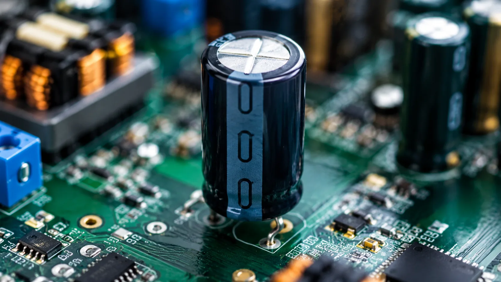
Electrolytic capacitors may also include polarity markings because many are polarized devices. A stripe commonly identifies the negative terminal on aluminum electrolytic capacitors, although users should verify the actual component markings rather than relying on assumptions. Circuit boards may also indicate positive and negative positions. Installing a polarized capacitor backward can cause poor operation, overheating, leakage, or failure. The µF value does not tell you polarity, so this information must be checked separately. When replacing components, matching capacitance while ignoring polarity is a common and potentially serious mistake.
Smaller capacitors may not have enough physical space to print a complete µF value. Instead, manufacturers may use numerical codes, abbreviated units, or markings based on picofarads. A common three-digit code uses the first two digits as significant figures and the third as the number of zeros in picofarads. For example, a capacitor marked 104 commonly represents 100,000 pF, which equals 100 nF or 0.1 µF. Learning these codes is particularly useful when working with ceramic capacitors. However, not every manufacturer or capacitor type follows exactly the same marking convention, so context still matters.
Some capacitors may use decimal notation without explicitly printing the µF symbol. A film capacitor might show a marking such as “0.47” with additional letters or voltage information. Depending on the component standard and context, that value may represent microfarads. This is why experience with capacitor types is helpful when interpreting unfamiliar labels. Component datasheets, circuit documentation, and physical design can provide additional clues. When uncertain, measuring capacitance with a suitable meter can help confirm a value after the component has been safely isolated from the circuit. Accurate identification is more important than guessing based solely on appearance.
µF, nF and pF: What Is the Difference?
Microfarads, nanofarads, and picofarads are different scales of the same basic capacitance unit. The farad remains the underlying SI unit, while the prefixes indicate fractions of a farad. A microfarad equals 10⁻⁶ farad, a nanofarad equals 10⁻⁹ farad, and a picofarad equals 10⁻¹² farad. Each step between these common units differs by a factor of 1000. Therefore, 1 µF equals 1000 nF, and 1 nF equals 1000 pF. This relationship makes conversions straightforward once the order of the prefixes is understood.
To convert microfarads to nanofarads, multiply the µF value by 1000. A 0.22 µF capacitor therefore equals 220 nF. A 4.7 µF capacitor equals 4700 nF. To convert nanofarads back to microfarads, divide by 1000. These conversions are especially useful when a schematic uses one unit but an available component is labeled with another. Recognizing equivalent values prevents people from mistakenly assuming two differently written values represent different capacitors. The underlying capacitance remains identical when the conversion is performed correctly.
Picofarads are frequently used for very small capacitance values, especially in radio-frequency, oscillator, and high-speed electronic circuits. To convert nanofarads to picofarads, multiply by 1000. Therefore, 10 nF equals 10,000 pF. Since one microfarad equals one million picofarads, even a relatively small µF value can appear very large when expressed in pF. This demonstrates why engineers choose units suited to the size of the number. Writing 0.000047 µF is less convenient than writing 47 pF. Good unit selection improves readability and reduces opportunities for decimal errors.
A useful example is the common 0.1 µF capacitor. The same value can be written as 100 nF or 100,000 pF. All three descriptions are electrically equivalent in terms of nominal capacitance. However, component type and other specifications can still differ. A 0.1 µF ceramic capacitor and a 0.1 µF film capacitor share the same nominal capacitance but may behave differently in particular circuits. Unit conversion therefore confirms value equivalence, not complete component interchangeability. Engineers still need to check voltage rating, tolerance, dielectric type, temperature characteristics, and application requirements.
Learning the unit sequence makes capacitor reading much easier. From larger to smaller common values, the order is farad, microfarad, nanofarad, and picofarad. Each move toward the smaller unit multiplies the numerical value by 1000. Each move toward the larger unit divides it by 1000. Remembering this pattern eliminates the need to memorize every conversion individually. It also helps when checking whether a calculated answer is reasonable. If a conversion produces a result that seems far too large or small, reviewing the direction of the conversion can quickly reveal a mistake.
Why Is µ Sometimes Written as uF?
The correct technical symbol for microfarad is µF, using the Greek lowercase letter mu followed by a capital F. However, many keyboards, software systems, databases, and older electronic displays do not make the µ symbol easy to enter. As a practical substitute, engineers and manufacturers often write “uF.” The Latin letter u visually resembles µ and has become widely understood as an informal representation of the micro prefix. Therefore, 10 uF and 10 µF normally mean the same thing. This alternative notation is especially common in online discussions, circuit design software, parts databases, and plain-text documentation.
Older computer systems played an important role in making uF common. Early character sets did not always support Greek letters or specialized scientific symbols consistently. Engineers needed a simple notation that could be typed using standard English keyboard characters. The lowercase letter u became a convenient substitute for µ. Even though modern Unicode systems support the proper micro symbol, the ASCII-friendly version remains common because it is easy to type and search. This historical habit explains why both forms appear throughout electronics documentation. Neither should be confused with a different capacitance unit when the surrounding context clearly indicates microfarads.
Capitalization can vary in informal sources as well. You might see uF, UF, MFD, or other legacy forms printed on components or equipment. “MFD” has historically been used to mean microfarad in some capacitor labeling, especially on older equipment and certain motor capacitors. However, modern technical notation generally favors µF because it clearly follows SI conventions. A capital M normally represents mega in SI notation, so writing MF could create serious ambiguity. Understanding older markings is useful when repairing vintage equipment, but modern documentation should use standard units whenever possible.
Search engines and online parts catalogs may treat µF and uF as equivalent terms, but users should still read product specifications carefully. A listing titled “100uF capacitor” almost always means 100 microfarads. The same component may show “100 µF” in its datasheet or printed label. When ordering replacements, the more important factors are the actual capacitance, voltage rating, capacitor type, dimensions, tolerance, and other electrical characteristics. The typography itself usually does not change the value. Recognizing equivalent notations simply helps users search for and identify components more efficiently.
The easiest rule is that µF is the standard symbol, while uF is a common typing substitute. Both generally refer to microfarads in electronics contexts. When writing formal technical material, µF is preferable because it follows standard scientific notation. When entering values into systems that cannot display Greek characters, uF is usually acceptable and widely understood. Awareness of both forms prevents confusion when reading labels from different manufacturers or decades. It also makes searching for replacement capacitors easier because online listings may use either notation.
Common Microfarad Values and Their Uses
Small microfarad values such as 0.1 µF, 0.22 µF, 0.47 µF, and 1 µF frequently appear in signal processing, timing, coupling, and decoupling applications. A 0.1 µF capacitor is especially common near integrated circuits because it can help reduce high-frequency noise on power supply lines. Depending on the circuit, ceramic or film capacitors may be selected for these values. The capacitance alone does not determine the component’s purpose because placement, circuit impedance, and operating frequency also matter. Still, recognizing these common values makes it easier to interpret circuit diagrams and component layouts.
Values such as 4.7 µF, 10 µF, 22 µF, and 47 µF appear frequently in general electronic circuits. These capacitors may support power supply filtering, audio coupling, voltage stabilization, timing, and many other functions. Electrolytic, tantalum, ceramic, or other capacitor technologies may be used depending on voltage, frequency, size, and performance requirements. Modern ceramic capacitors can provide surprisingly large capacitance in compact packages, although their effective capacitance may change under applied voltage depending on dielectric characteristics. This is one reason experienced designers consider more than the number printed on the component.
Larger values such as 100 µF, 220 µF, 470 µF, and 1000 µF are commonly associated with power supply filtering and energy storage. Electrolytic capacitors are frequently used because they can provide high capacitance in relatively compact packages. In a rectified power supply, these capacitors can help smooth voltage by storing energy when the input is high and releasing it when the input drops. The required value depends on load current, ripple tolerance, operating frequency, and circuit design. Simply installing the largest available capacitor is not always beneficial because charging current and circuit behavior must also be considered.
Motor capacitors often use values measured in microfarads as well. Start capacitors can provide phase shift and starting torque for certain single-phase motors, while run capacitors remain connected during normal operation in appropriate motor designs. Their capacitance values and voltage ratings are selected specifically for the motor. Replacing a motor capacitor with a random capacitor of similar physical size can cause poor performance or damage. Motor capacitors also use construction designed for their electrical role. The µF marking helps identify the required capacitance, but the replacement should match the intended capacitor type and manufacturer specifications.
Very large capacitance values may reach thousands or tens of thousands of microfarads in certain power electronics applications. At some point, values may also be expressed in millifarads or even farads, particularly with supercapacitors. A 10,000 µF capacitor equals 0.01 F, for example. Supercapacitors can have values measured in whole farads or much higher because they are designed for substantial energy storage compared with ordinary electronic capacitors. These examples show how broad the capacitance range can be. Microfarads remain especially common because they sit within a practical range for countless everyday electronic and electrical applications.
Microfarad vs Farad: How Are They Related?
The farad, represented by F, is the base SI unit of capacitance. A microfarad is simply a smaller fraction of that unit. The prefix micro means one millionth, so one microfarad equals 0.000001 farad. Conversely, one farad equals 1,000,000 microfarads. This relationship is similar to how one meter relates to micrometers or one ampere relates to microamperes. Using prefixes allows engineers to express very small or very large values without writing long strings of zeros. The microfarad therefore does not represent a different physical property; it is simply a convenient scale of the farad.
A full farad is large compared with many traditional electronic capacitors. For decades, most common circuit capacitors were measured in picofarads, nanofarads, or microfarads. Advances in capacitor technology have made farad-scale energy storage much more common in supercapacitors, but ordinary circuit design still uses smaller units extensively. A 100 µF electrolytic capacitor, for example, equals only 0.0001 F. Writing 100 µF is far easier to interpret than repeatedly dealing with four decimal places. Unit prefixes therefore improve both communication and practical component labeling.
Converting from farads to microfarads requires multiplying by one million. For example, 0.002 F equals 2000 µF. Converting in the opposite direction requires dividing the microfarad value by one million. Thus, 470 µF equals 0.00047 F. These conversions are straightforward but require careful attention to decimal placement. Calculator errors can happen when users confuse microfarads with millifarads or nanofarads. Writing the unit at each step can reduce mistakes. Scientific notation is also useful because micro corresponds directly to a factor of 10⁻⁶.
Millifarads sit between farads and microfarads in the metric prefix system, although the unit is less commonly printed on ordinary capacitors. One millifarad equals 0.001 F or 1000 µF. Therefore, a 4700 µF capacitor could also be described as 4.7 mF. Many manufacturers still prefer the microfarad form because technicians are accustomed to seeing electrolytic capacitors labeled in µF. Supercapacitor specifications, however, are often expressed directly in farads once capacitance becomes sufficiently large. The choice of unit usually reflects convention and readability rather than any difference in the underlying capacitance.
Understanding the farad relationship helps make the microfarad symbol more intuitive. Instead of treating µF as an unfamiliar electronics abbreviation, it can be read systematically using metric prefixes. The µ means divide a farad by one million, while F identifies capacitance. The same logic applies to nF and pF at smaller scales. Once this system becomes familiar, even unusual capacitance values are easier to interpret. Engineers can move between units depending on whichever representation is most convenient. This flexibility is one reason SI prefixes are so useful in technical communication.
How Capacitance Affects a Circuit
Capacitance affects how a circuit responds to changes in voltage and current. A capacitor stores energy in an electric field when voltage is applied across its terminals. When the surrounding circuit conditions change, the capacitor can release that stored energy. The rate at which a capacitor charges and discharges depends on the capacitance value and the resistance or other circuit elements connected to it. Larger capacitance generally means more charge can be stored at the same voltage. This behavior allows capacitors to smooth power supplies, create timing delays, filter signals, and perform many other useful electrical functions.
In power supply circuits, capacitance helps reduce voltage ripple. After alternating current is rectified, the resulting voltage may rise and fall rather than remain perfectly steady. A smoothing capacitor charges near the peaks and releases energy between them, helping maintain a more stable output. Increasing capacitance can often reduce ripple under the same conditions, although there are practical limits and tradeoffs. Larger capacitors can create higher inrush current when power is first applied. Designers therefore select capacitance based on load, ripple requirements, physical size, cost, and component ratings rather than simply maximizing the µF value.
In timing circuits, capacitance can influence how long a voltage takes to rise or fall. When a capacitor charges through a resistor, the combination creates an RC time constant. Increasing either the resistance or capacitance increases the characteristic charging time. This principle is used in delays, oscillators, pulse shaping, and many control circuits. A small change in capacitance can therefore alter timing performance significantly. Replacing a timing capacitor with the wrong µF value may cause a device to operate too quickly, too slowly, or not at all. Accurate capacitance becomes essential when timing is part of the design.
Capacitors also affect how signals at different frequencies move through circuits. Their opposition to alternating current changes with frequency, which allows them to participate in filters, coupling networks, and frequency-selective circuits. Larger capacitance generally presents lower capacitive reactance at a given frequency. This helps explain why different capacitor values are chosen for audio frequencies, power supply filtering, and high-frequency electronics. The relationship between capacitance and frequency is fundamental to circuit design. The µF marking therefore carries information that directly influences how a circuit responds across different operating conditions.
Energy storage is another important effect. The energy stored in a capacitor depends on both capacitance and voltage. Increasing capacitance increases potential stored energy when voltage remains the same. However, higher voltage can dramatically increase stored energy as well. This is why large capacitors in power equipment can remain dangerous even after a device is switched off. Proper discharge procedures may be required before servicing circuits containing high-energy capacitors. Understanding microfarad values helps estimate behavior, but safe handling also requires attention to voltage and circuit design. Capacitance is useful precisely because capacitors can temporarily hold electrical energy.
How to Choose the Right µF Capacitor
Choosing the correct capacitor begins with matching the required capacitance. If a circuit specifies 100 µF, the replacement should normally have the same nominal capacitance unless the design documentation explicitly allows another value. Some applications tolerate small differences, while timing, filtering, motor, or tuned circuits may be more sensitive. The component’s tolerance indicates how far its actual capacitance may vary from the nominal rating. A capacitor marked 100 µF does not necessarily measure exactly 100.000 µF. Designers account for expected tolerance when selecting parts, so arbitrary substitutions should be avoided.
Voltage rating is equally important. A capacitor must be able to withstand the maximum voltage it will encounter in normal and abnormal operating conditions according to the circuit design. Using a capacitor with too low a voltage rating can cause dielectric breakdown, overheating, leakage, or catastrophic failure. A replacement with a higher voltage rating may sometimes be acceptable, provided the component type, size, electrical characteristics, and application remain suitable. However, voltage rating should never be reduced below the design requirement. Capacitance and voltage must always be checked as separate specifications.
Capacitor type also matters because different technologies have different electrical characteristics. Electrolytic capacitors offer high capacitance but may have polarity and aging considerations. Ceramic capacitors can be compact and effective at high frequencies, but some types lose significant effective capacitance under DC bias. Film capacitors can offer stable performance and low losses in many applications. Tantalum capacitors have their own advantages and limitations. Replacing one technology with another simply because the µF value matches may produce unexpected results. Circuit requirements should guide the choice rather than capacitance alone.
Physical size and lead arrangement can also determine whether a replacement fits. Capacitors with identical electrical ratings may have different diameters, heights, lead spacing, or mounting styles. Printed circuit boards often provide limited space, particularly in compact electronics. Temperature rating is another consideration because components near power devices or inside enclosed equipment may operate in hot environments. Long-life electrolytic capacitors are often rated for specific operating temperatures and lifetimes. Choosing a component without considering physical and environmental requirements can lead to installation problems or premature failure even when the µF value is correct.
Specialized applications require additional specifications. Power supply capacitors may need low equivalent series resistance, or ESR, to handle ripple current efficiently. Motor capacitors must be designed for the appropriate AC operating conditions and duty cycle. Audio, RF, and precision circuits may require specific dielectric characteristics. Safety-rated capacitors used across mains or from mains to ground require proper safety classifications and should never be replaced with ordinary capacitors. The microfarad rating provides only one part of the selection process. Safe and reliable replacement requires considering the entire specification and the function the capacitor performs.
Common Mistakes When Reading µF Values
One common mistake is confusing microfarads with nanofarads or picofarads. Because capacitor values may be written in several equivalent forms, a decimal point can make a major difference. For example, 0.1 µF equals 100 nF, not 100 µF. Misreading the value by a factor of 1000 can cause a circuit to behave completely differently. Writing conversions carefully and keeping the unit visible helps reduce errors. When working from old schematics or unfamiliar component markings, verifying the intended unit is especially important. Small notation differences can represent very large changes in capacitance.
Another mistake is assuming that uF and µF represent different units. In most electronics contexts, uF is simply a keyboard-friendly way to write microfarads. A 47uF capacitor and a 47 µF capacitor therefore have the same nominal capacitance. Confusion may arise when users interpret the letter u as an additional unit prefix. Understanding the historical reason for this notation eliminates the problem. However, users should still be cautious with other unusual labels such as MFD or MF, especially on older equipment. Context and technical documentation can help determine what the manufacturer intended.
Ignoring voltage rating is another serious error. Two capacitors may both be marked 220 µF but have very different voltage ratings. A 220 µF 10 V capacitor is not automatically suitable for replacing a 220 µF 50 V part. The lower-voltage component could fail if the circuit exposes it to more than its rating. Physical size may also mislead users because smaller modern capacitors can sometimes have equal or better ratings than older larger components. Electrical specifications should always be checked directly. Visual similarity is not enough to determine safe interchangeability.
Polarity mistakes frequently occur with electrolytic capacitors. Users may focus on matching the µF value and overlook the positive and negative terminals. Installing a polarized capacitor backward can lead to leakage, overheating, venting, or other failure. Circuit board markings and capacitor stripes should be checked carefully before removal and installation. Taking a photograph before replacing components can help preserve orientation information. Non-polar capacitors exist as well, so the component type must be identified correctly. Capacitance alone does not indicate whether polarity matters.
A final mistake is assuming that any capacitor with the same capacitance and voltage rating is fully interchangeable. ESR, ripple current, temperature rating, tolerance, dielectric type, lifetime, and frequency behavior can all matter depending on the circuit. A replacement may technically match 100 µF and 25 V yet perform poorly in a switching power supply if its ESR or ripple-current rating is unsuitable. This is why component selection should consider application requirements. The µF marking is the starting point, not the entire specification. Careful matching improves both performance and reliability.
Conclusion
The microfarad symbol, µF, represents a unit of electrical capacitance equal to one millionth of a farad. It is one of the most common units printed on capacitors because many practical electronic components have capacitance values within this range. The Greek letter µ means micro, while the capital F represents farad. A value such as 47 µF therefore means forty-seven microfarads. Understanding this simple notation makes capacitor labels, circuit diagrams, and parts catalogs much easier to read. It also provides a foundation for learning how capacitance influences electrical circuits.
Microfarads belong to a broader system of capacitance units that includes farads, nanofarads, and picofarads. One microfarad equals 1000 nanofarads and one million picofarads. These relationships allow the same capacitance to be expressed in different forms depending on which unit is easiest to read. For example, 0.1 µF equals 100 nF and 100,000 pF. Learning these conversions is especially useful when replacing capacitors or interpreting different schematic conventions. Consistent unit conversion helps prevent errors caused by misplaced decimal points or unfamiliar labels.
The µF value is important, but it should never be considered by itself when selecting or replacing a capacitor. Voltage rating, polarity, capacitor type, tolerance, temperature, ESR, ripple current, and physical size may all affect suitability. A replacement can have the correct microfarad value and still be inappropriate for the circuit. This is particularly important in power supplies, motor circuits, mains-connected equipment, and precision electronics. Reading the complete component specification is therefore essential. The capacitance value tells you how much capacitance the component provides, not every characteristic of its performance.
It is also useful to recognize alternative markings. The notation “uF” is widely used as a practical substitute for µF because standard keyboards and older systems may not provide the Greek micro symbol easily. In most electronics contexts, the two forms mean exactly the same thing. Older components may use additional legacy markings, while small capacitors may rely on coded values rather than printing microfarads directly. Familiarity with these conventions makes it easier to work across new and old electronic equipment. When a marking remains uncertain, technical documentation or measurement can provide confirmation.
Ultimately, learning how to read the microfarad symbol is a basic but valuable electronics skill. It helps explain capacitor values, unit conversions, component selection, and circuit behavior. Whether you are reading a 1 µF ceramic capacitor, a 470 µF power supply capacitor, or a motor capacitor rated in microfarads, the same unit principle applies. The µ identifies a millionth, and F identifies the farad. Once that relationship becomes familiar, capacitor labels stop looking mysterious. Understanding µF creates a simple gateway into broader concepts such as capacitance, filtering, timing, energy storage, and electrical design.
Frequently Asked Questions About Microfarads
What does µF mean on a capacitor?
µF means microfarad, a unit used to measure capacitance. One microfarad equals one millionth of a farad, or 0.000001 F.
Is uF the same as µF?
Yes, uF is commonly used as a plain-text substitute for µF when the Greek micro symbol is unavailable. A capacitor marked 10uF therefore normally means the same thing as 10 µF.
How many nanofarads are in 1 µF?
One microfarad equals 1000 nanofarads. Therefore, 0.1 µF equals 100 nF, while 2.2 µF equals 2200 nF.
What does 100 µF 25 V mean?
It means the capacitor has a nominal capacitance of 100 microfarads and a voltage rating of 25 volts. The capacitance and voltage ratings describe different electrical characteristics and both should be considered during replacement.
Can I replace a capacitor with the same µF but higher voltage?
A higher voltage rating may often be acceptable when the capacitance, capacitor type, physical size, polarity, ESR, and other required characteristics are also suitable. The replacement should never have a voltage rating below what the circuit requires.